Someone was asking on ARocket about where to start with building a differentially throttled hovering vehicle. Lots of advice were given by various people. I’ll show some stuff I quickly sketched back in 2007 with Simulink. It’s such an easy to use and awesome software (especially compared to a recent short battling with LabView), that whipping up any control system or any process or system models are really quick jobs.
This is just some really trivial basics, it doesn’t take into account nearly enough things to produce a real hovering vehicle. I guess it’s just a way to show how things could be started.
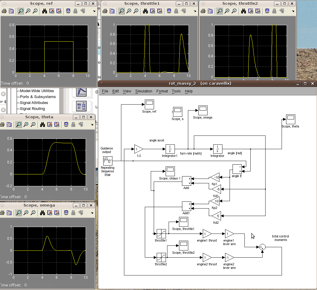
So, here’s a pic of a simple one-dimensional rotational feedback system. Just tested some feedback coefficient values for the PD controller.
1) You can see the placeholder “guidance algorithm” output at the top left “scope” graph. This is the reference or target value of the angle where we want the vehicle to be. At the start it’s giving a desired angle of zero radians, then from 4 seconds onwards it suddenly wants 0.5 radians, then again zero after 6 seconds. This could be holding a tilt for a while for getting up some lateral velocity for a transverse move.
2) Below that, you see Theta, the angle that the vehicle actually had during the simulation. It follows the desired angle quite nicely. Below Theta, there’s omega, the angular velocity.
3) The tilting is done by throttling the two thrusters. At top center and top right you can see the values of the throttles. Since this thing only concerns tilt and not stationary hovering, the throttles are at zero when the vehicle is at the right attitude (reference=Theta) and there’s no angular velocity. When the refence is moved, at 4 seconds, throttle 1 shoots up for a while and the vehicle starts tilting. At around 4.8 seconds the other thruster, throttle 2 shoots up to stop the rotation, since the vehicle is nearing the desired angle.
You can see from the block diagram how the error value, E = theta – reference is calculated. And also omega is used. From these the throttle values are calculated, simply by Throttle1 = E*Kp1 + omega*Kd1 and so on. By fiddling with the Kp and Kd values, called gains, one can tune the system. The values currently are just some I quickly tried back then. This Simulink model actually has a bug, a sign error. The error signal’s difference calculation is backwards, hence Kp1 and Kd1 are negative. It should be the other way around.
You can tune the model. Basically, raising the proportional values makes the system faster (reach desired values quicker) but gives overshooting and can make the system oscillate unstably. Higher derivative gains remove the tendency to oscillate, but the system becomes more sensitive to noise (noise can after all have large derivatives). If the vehicle had problems of always staying some amount off from the final required attitude value, an error integrator could be added that would fine tune the vehicle a little (making it a PID controller). This is probably not needed here though – the guidance system could notice if the vehicle travels somewhere it doesn’t want it to go.
The MDL file for the above is available here.
This is just a very quick first brush analysis, there are much much more things to take into account. The other tilt axis, roll, the need to actually stay airborne (altitude or vertical velocity feedback loop) that ties into the throttle values too. One could abstract this tilt in one axis to a single control block, and produce another similar block for altitude holding, then couple these blocks into a whole system of altitude and tilt holding (by mixing the throttle values). This should avoid clutter and enable one to isolate problems.
Also, one should add some noise to the sensed angle vs real angle as gyro noise seems to be a real issue for VTVL vehicles. One wouldn’t want to tune a PD controller’s values in a noiseless simulator and then find out it gets wildly out of control in the real world. Even when not simulating noise, one can be quite conservative with the tuning values, and that helps too. The throttles probably would be another source of errors as well, if one used ball valves like here. One could also use pulse width modulated solenoids (John Carmack is fond of those for quick work) and those should be modeled. Digital valves (for liquids) have also improved lately, and hydraulics uses are emerging.
I’ve only done real world PID stuff on lab experiments. But it’s still very cool to see it work. It can balance a ball on an unsteady position on a moving cart, which humans have trouble with using a joystick, and the math in the controller is not complex since linear approximations can be used for that problem.


I sincerely got a kick out of your article. I don’t really have a lot to say in reply, I only wanted to comment to reply with wonderful work. good luck in 2010.